Octopus Eight Servo Driver Schematics (This is for the Original Octopus based on the SX chip)
The control code in SX/Basic can be downloaded by clicking here. Learn more about the SX chip and SX/B, the BASIC language for SX at the Parallax website.
Circuit Description
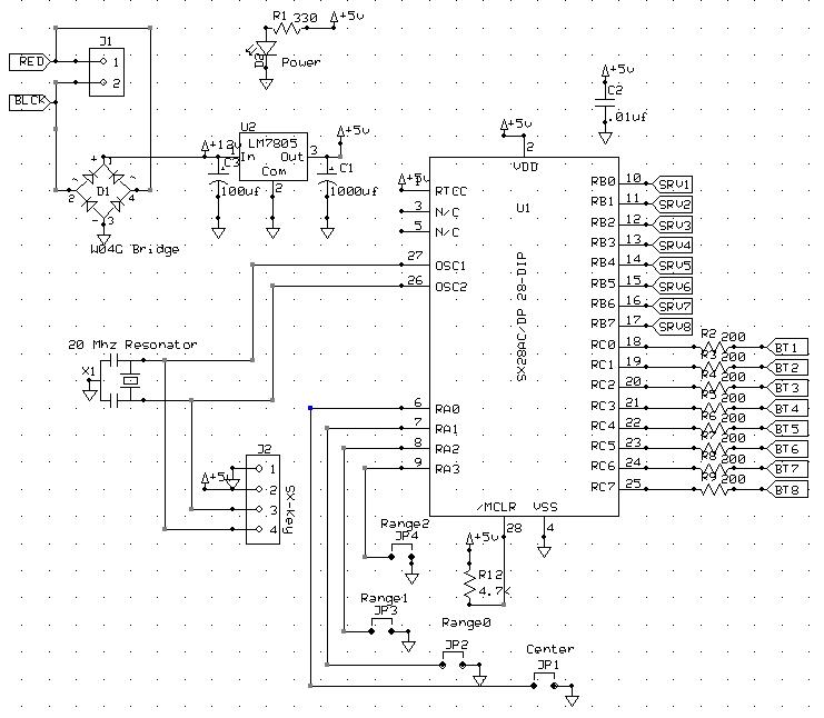
Power is
input through a bridge rectifier which allows the use of DC or AC
voltage. U1 is an SX28AC
microprocessor running at 20 MHz as set by the ceramic resonator X1.
This provides the timing necessary to
precisely time the pulse-widths for the servos. The SX-Key connector
can be used to program the chip from a USB port of a Windoze PC with an
SX-Blitz.
The more expensive SX-Key also works but the debugging features will
not work on this board, so only purchase it if you are interested in
other development using SX chips. The SX is a very fast chip designed
to program virtual peripherals and is well suited for this application. The SX receives inputs from switches (BT1-8) connected to ground on one side. In the closed position the switch pulls the wire low and in the open position an internal pullup resistor in the SX keeps the line high. The input can be any open collector logic that is active low. The control pulses for the servos (SRV1-8) are
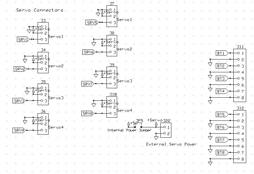
output through 3-pin connectors.
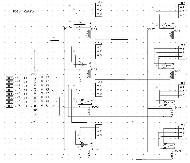
The relays are optional and are designed to be used to power
the frogs. However, the relays can be used to control any device that
draws up to 1 amp. An example would be a crossing gate that is
activated when a turnout is in a particular position. The relays are
buffered by a ULN2803 Darlington transistor array that also provides
diode flyback protection. If the relays are used then 12-15 volts
should be provided to the board to provide the proper voltage for the
relay coils.